Masters Degree in Guidance and Navigational Contro...More
Sections
As many electrical systems and equipment operate only in AC, many aircrafts employ a completely AC system as well as a DC system. Modern aircrafts uses AC power system but light aircraft tend to operate mostly on electrical systems using DC power. So DC batteries can easily act as a backup power source. Some modern aircrafts uses a small AC system in that case AC power required for the system is produced using AC inverters. Many inverters supply both 26V AC as well as 115V AC. Aircrafts can be designed to use either voltages or both simultaneously provided that both voltages are distributed through separate busses.
Various parts of an aircraft electrical system:

Figure 1: Simplified Electrical System of Aircraft
Stores electrical energy and its main functions are to provide power supply to start the engine, ground power, emergency power, improving DC bus stability and fault clearing. Batteries store only a limited supply of backup power if the alternator or generator fails. The battery must have the capacity to supply essential load for 30 minutes. Selection of batteries for various aircrafts depends on the following characteristics.
Mainly two types of batteries are used in aircrafts. Most small aircrafts use lead acid batteries and most commercial aircrafts use nickel cadmium batteries.
Dry charged cell lead acid batteries are also called flooded or wet batteries. They are assembles with fully charged and dried electrode plates. The electrolyte is added when the battery is placed in service. The battery life starts when the electrolyte is added. Aircraft storage batteries consists of 6 or 12 lead acid cells connected in series. The open circuit voltage (voltage of the battery when the no load is connected) of the 12 cell battery is approximately 24V. When the Battery is charges, oxygen is produced on the positive electrode and it escapes from the cell. At the same time hydrogen is generated in the negative electrode and it also escapes from the cell resulting in gassing of cells and loss of water. Flooded cells require periodic water replacement.
VRLA batteries are called sealed batteries. The electrochemical reactions in these batteries are similar to that of a flooded battery except that gas recombination mechanism is predominant in the former. VRLA batteries are used in aviation and turbine powered aircrafts and sometimes they are authorized replacement for nickel cadmium batteries. When VRLA batteries are charged, oxygen combines with lead at the negative electrode in the presence of H2SO4 to form lead sulphate and water. The recombination prevents the formation of hydrogen in the negative electrode so that no water is lost during charging. Some amount of water is lost during self-discharging which is so small. As a result no provision for water replacement is provided. There is a pressure release safety valve that may open if the battery is overcharged.

Figure 2: Lead Acid Battery used in Aircraft
NiCd batteries consist of a metallic box usually made of stainless steel, titanium, painted steel or plastic coated steel containing a number of individual cells. These cells are connected using a highly conductive nickel copper link to obtain 12V or 24V. NiCd batteries have a ventilation system to provide cooling during normal operation and to allow escape of gases produced during overcharging. The ventilation system prevents the damage of the battery from excessive rate of overcharge, discharge or negative charge. These batteries are rechargeable. NiCd batteries fitted with the aircrafts contain a fault protection system that monitors the condition of the battery.
Alternators are the power source to the aircrafts electrical system. They are driven by the engine by means of belts. Depending on the type of electrical system the alternators can be of two types
DC alternator contains two main components, the armature winding and the field winding. The field winding rotates inside the armature and produces a magnetic field. By the process of electromagnetic induction a voltage is developed in the armature. The voltage developed in the armature is fed to the aircraft electrical system and it powers all the electrical loads of the aircraft. The armature wiring is a three-phase star delta wiring so the voltage produced is a three-phase AC voltage. Since the AC power generated is not compatible with DC electrical loads it needs to be rectified. So the armature output is fed to a rectifier assembly which converts AC to DC. The output of the rectifier assembly is a relatively small ripple DC. The rectifier assembly is mounted on the alternator case.
AC alternators are found only on aircrafts that uses a very large amount of electrical power. All transportation category aircrafts like Boeing 757 or the Air Bus A-380 uses an AC alternator driven by both engines. The aircraft also have an auxiliary power unit. In most transport category aircraft there is at least one more AC backup power source like AC inverter or a small alternator driven by ram-air turbine (RAT). AC alternator produced an AC output. Nowadays brushless alternators are used in large aircrafts. The need of brush is eliminated by a combination of three generators namely, the main AC alternator, the exciter generator and the pilot exciter generator.
The exciter permanent magnet and armature starts the generation process and the output from exciter armature is rectified and sent to the pilot exciter field. The pilot exciter field produces a magnetic field and induces power in the pilot exciter armature by electromagnetic induction. The output from the pilot exciter armature is fed to the main alternator control unit and sends back to the exciter field. As the rotor continues to rotate the main AC alternator field generates power into the main AC alternator armature by electromagnetic induction. The output of AC armature is a three-phase AC and is used to power various electrical loads.
Some alternators are cooled by circulating oil through internal components of the alternator. The oil used for cooling is supplied from the constant speed drive assembly and often cooled by an external oil cooler assembly. The oil level is critical and checked on a routine basis.
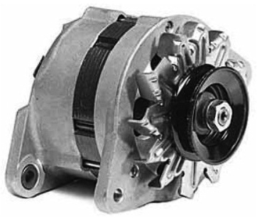
Figure 3: Aircraft's AC Alternator
DC generators convert mechanical energy into electrical energy (Direct Current) and are found in light aircrafts. They are also driven by the engine by means of a belt arrangement. But it doesn’t produce enough current at low RPM to operate the entire electrical system. Aircrafts with generators use battery power at low engine RPM. Nowadays in most aircrafts DC alternators are used as a replacement for DC generators. The main short coming of a DC generator is that it always requires a control circuit for maintaining the correct voltage and current for present electrical conditions of the aircraft. The aircraft maintain a nominal voltage of around 14V or 28V. There are three types of DC generators namely series wound, shunt (parallel) wound and compound (series-parallel) wound.
Series wound DC generators are usually not used in aircrafts due to their poor voltage and current regulation. Aircrafts using shunt wound DC generators also use an automatic control device such as a voltage regulator. Compound wound generators are used in aircrafts as it produces relatively constant output even if there is a load variation. DC generators are rated for its voltage and power output. They are designed to operate at a specified voltage, either 14V or 28V. Aircraft voltage depends upon which battery is selected. The generator selected must have an output voltage slightly above the battery voltage.

Figure 4: Aircraft's DC Generator
The main function of the ignition system is to ignite the fuel air mixture by providing a high energy spark at the right time thereby initiating the engine’s power stroke. The main electrical components of an ignition system are
Magnetos are self-contained ignition unit that produce pulses of electricity to the two spark plugs. They are used in the internal combustion ignition engine. Magnetos convert mechanical energy into electrical energy. Magneto is a field generator which contains a rotating magnet inside a coil. The rotating magnetic field generates a voltage in the coil (primary coil). The voltage in the primary coil is then converted into a very high voltage by a secondary coil which has more number of turns than the primary coil. The current flow in the circuit is interrupted by a breaker contact in the primary coil generating a high peak voltage in secondary coil as the magnetic field collapses. The distributors and high voltage leads carry this peak voltage to the spark plug. Two magnetos are connected in such a way that one drives the top spark plug and the other drives the bottom spark plug. Magnetos do not use power from the electrical system of the aircraft so that in case of a flat battery during flight the aircraft engine continues to run.
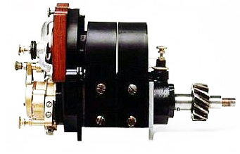
Figure 5: Magneto
A spark plug has a central electrode and a metal body which are screwed into the cylinder. The central electrode is insulated from the engine by means of a ceramic insulation. The spark plug contains a resistor which provides a short duration spark, supress radio frequency interference to some degree and also protects the electrode from corrosion. Two spark plugs with separate ignition circuits are used for each cylinder for redundancy, better ignition and combustion of the fuel air mixture and safety.
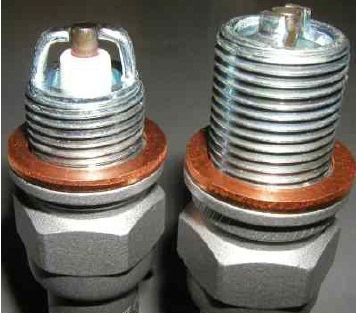
Figure 6: Spark Plugs
They are projective devices which protect the system from electrical overload as overload can cause damage to the electrical system. Fuses have an internal metal wire or strip that melts when excess current flow through it. Circuit breakers have a protective switch that trips during an overload condition. Circuit breakers can be reset manually instead of replacing it. Circuit breakers are preferred as they are resettable.
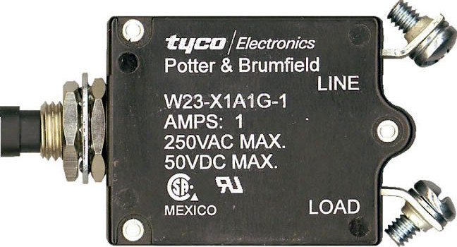
Figure 7: Circuit Breaker
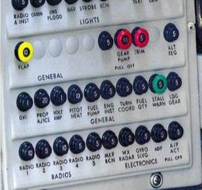
Figure 8: Circuit Breaker Control
Voltage regulator controls the rate of charge to the battery and also stabilises the alternator or generator output. The voltage regulators controls the alternator output by adjusting it field current control. The operation of voltage regulators in DC alternator and DC generator are similar. Most modern aircrafts uses either vibrating relay or solid state regulators.
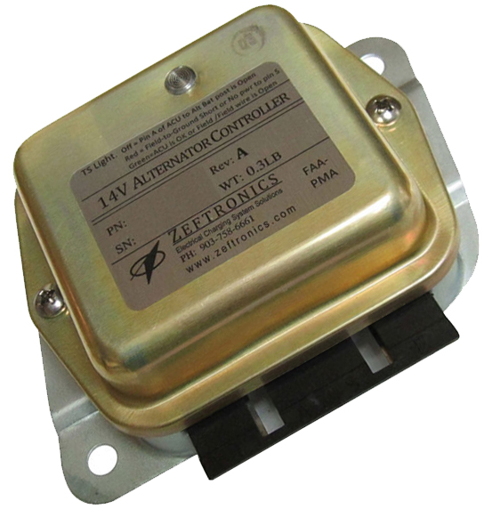
Figure 9: Voltage Regulator
The vibrating-relay regulator monitors the generator/alternator output and control generator/alternator’s field current. If the regulator senses the system voltage too high, the relay point opens and the current in the field circuit travels through a resistor. Thus generator output is lowered as the resistor lowers the field current.
They are also called Aircraft Control Units (ACU). These regulators are static devices so they are reliable and provide better regulation than vibrating-relay regulators. It relay on transitory circuitry to control alternator field current and alternator output. Solid state regulators control the alternator field current by continuously monitoring the alternator output. These regulators also provide protection against over current, over voltage or under voltage and also monitors alternator internal defects such as faulty diode. In certain situations of system malfunction the ACU also provide a warning indication to the pilot. The key component in this type of voltage regulator is a zener diode.
It turns electrical system ON or OFF. It controls the entire electrical system except the magneto ignition system including interior and exterior lights, radio, fuel gauges, pumps, engine starter motor. Some alternators are equipped with battery switch and alternator switch. The alternator switch disconnects the alternator from the entire electrical system in case of alternator failure.

Figure 10: Master Switch
Ammeters are used to monitor electrical system performance. There are two ammeters in most aircrafts
In some aircrafts there are only indicator lights for load indication.
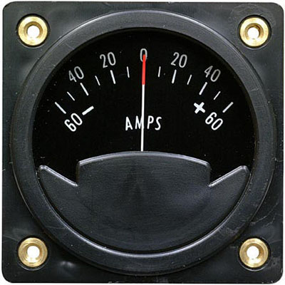
Figure 11: Aircraft Ammeter
They are used to power the electrical system from an external power supply. They are very useful in staring engine in cold weather. GPUs can be either fixed or mobile. Fixed type GPUs can provide power at 400Hz through a permanently installed installation to supply power to parked aircrafts. The conversion of main power to 400Hz is either done centralised or at the point using frequency converters. Balancing of the system is difficult in centralized power system. Mobile powered units can be deployed and are mounted on a vehicle and deliver power by utilising diesel generators
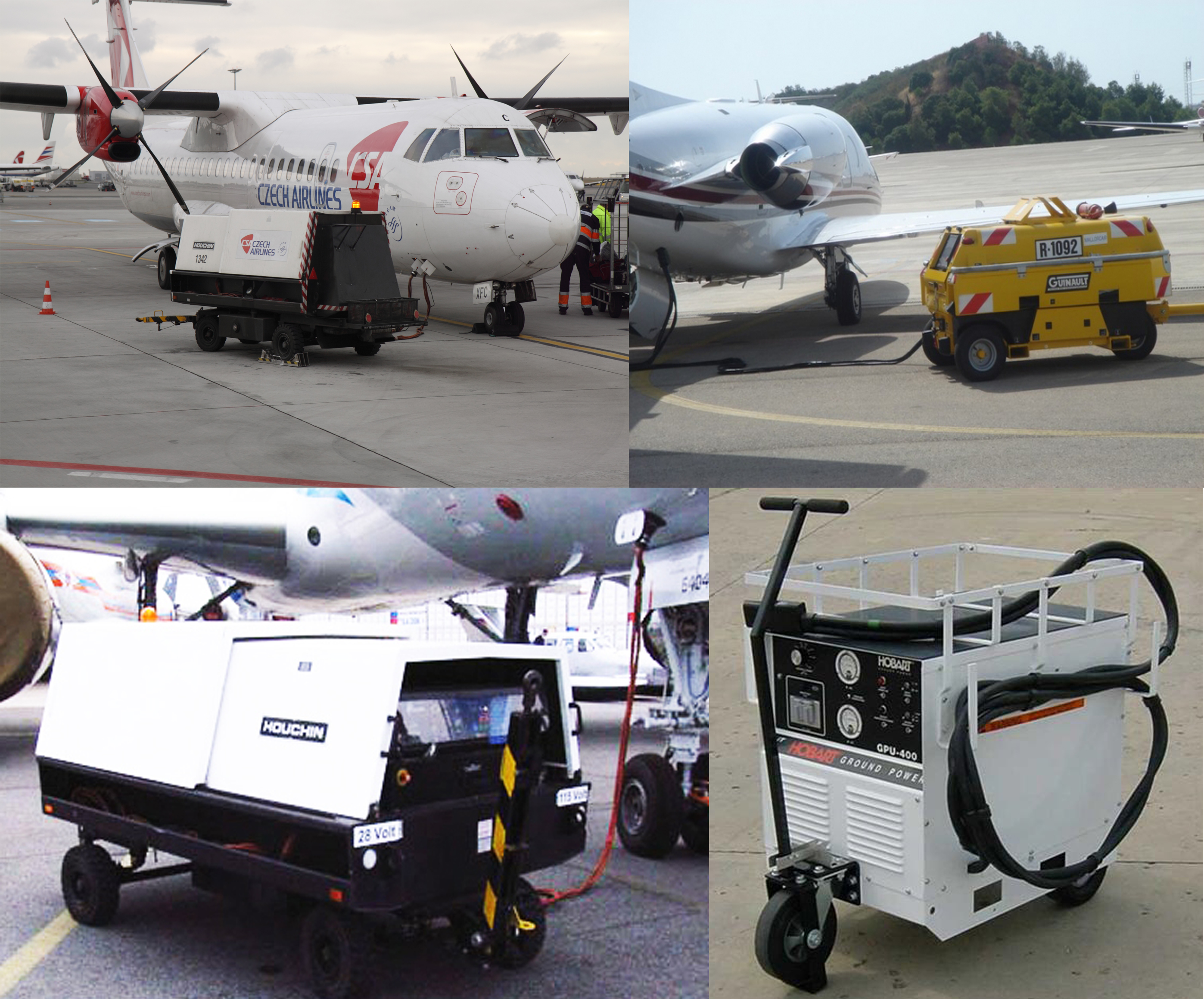
Figure 12: Mobile Ground Power Unit
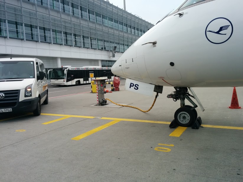
Figure 13: Fixed Ground Power Unit
Sections